VIBRATION MECHANICAL THEORY
Vibrating phenomena play a key role in mechanical engineering plant because of their effects on the dynamic behaviour of machines and their parts. These phenomena can be studied only if the system is brought back into a diagram, where we focus on and analyse its main vibration sources along the three main axis. Most of the time, this simplification is enough to study the vibration.
Vibrating systems, studied in mechanics of machinery, can be divided in two classes:
- with free vibrations
- with forced vibrations
Free vibrations occur in the absence of external forcing, that is to say when no external forces influence the system; in this case, the system will oscillate with one of its own frequencies and depends on the distribution and the stiffness of the system mass only. Forced vibrations occur under the excitation of external forces such as motor-driven forces. When excitation is driven by oscillations, the system vibrate at that frequency, but if this frequency equals one of its natural frequencies, the system is said to be in a state of resonance, generating of oscillations with higher amplitude. The Tacoma Narrows Bridge failure is an example of the effects caused by vibrations. On November 7, 1940 in the State of Washington, the bridge entered in resonance condition even wind was only 72 Km/h. Under such a particular condition, oscillations increased so much that they induced continuous vibrational waves along the road surface, caused the bridge structure to twist and, ultimately, to collapse. Actual vibrating systems are all subjected to damping, given the energy dissipation caused by friction or other resistance. Reduced damping effects do not influence the system natural frequencies; on the other hand, when it is strong, they play a key role in frequencies near to resonance. Mechanical vibration is characterized by :
- Amplitude (Dm/2 ): maximum variation from a reference value
- Frequency (fn): the number of oscillations within a time unit.
CONVEYORS ACTUATED BY CRANK-SHAFT DRIVEN DEVICE: INTRODUCTION
VIB oscillating mounting technology gives the chance to create high-performance oscillating conveyors that carry material of different type and size. VIB elastic mounts help to produce highly advanced conveyors compared to the traditional ones and provide the following improvements:
- It makes design and production much easier
- It give more savings to the production
- Long life and reduced maintenance
- Several applications/solutions: conveyors, screens, shakers, feeders, calibrators, etc.
The vibrating conveyors produced with VIB oscillating elements allow to propagate the vibrations generated by an eccentric along forward movement direction of the material. Vibrating conveyors – mounted with VIB technology - can be used to design and produce vibrating screens for fluid-smooth movement (conveyors) as well as jumping-movement (screening and calibration). Fluid vibrating machines are used at low frequencies (2Hz) and high amplitudes (max approx. 30 cm) and are suggested for bulk, big size material. Hopping-jumping movement conveyors work at high frequencies (up to 10 Hz) and reduced amplitudes (max approx. 2 cm). These conveyors are largely used in the mining-quarrying industry, fruit and vegetable processing, tobacco processing, recycling, flour-mill sifting, fodder mixing, etc.
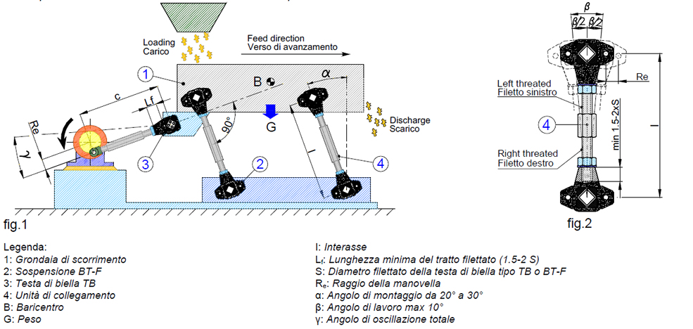
The system shown in fig. 1 is the most simple and inexpensive method to build conveyors for medium to long sized loose-material. This system consists of a sliding chute (1) supported by oscillating mountings (2) actuated by a crank-shaft drive device (3). These conveyors are used with rigid structures and are firmly fixed to the ground because the vibrating channel may work with accelerations up to 1.7 g. For these reasons, correct calculating of the machine is essential, while the appropriate choice of the VIB elastic elements improves the vibration absorption and optimizes the execution of the vibrating channel.
|
Usual feature for this type of plant |
|
|
Acceleration |
1,1 ÷ 1,7 g |
|
Feed speed |
6 ÷15 m/min |
|
Conveyor Lenght |
12 ÷ 15 mt |
This system consists of a chute supported by suspensions, each formed by 2 BT-F and actuated by a connecting rod TB that acts as an elastic bearing. This simple application can be used anytime dynamic forces are not too high because BT-F are charged with all loads and stresses. Fig. 2 illustrates the ideal design of a suspension using one connecting unit obtained by turning an hexagonal bar. Bar-end must be right-hand threated and left-hand threated respectively: this allows unavoidable adjustments of the interaxle distance which can be done with a wrench when setting up the system. In VIB range, oscillating mountings TP-S or TP-F are designed for use with similar engineering systems but with fixed suspension interaxle distance. During the design phase, power can be reduced by making the plant work under resonance condition, that is to say under a frequency near to the system one. Under this particular condition, the oscillation amplitudes increase a lot and giving the chance to reduce motor drive power with higher structure stresses.
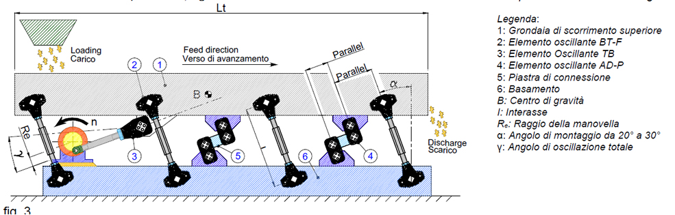
The vibrating system is the same as previous one with two or more pairs of elastic accumulators mounted between the channel and the base as you can see on pag F-23/25. The elastic element AD-P allows these advantages. This system allows to keep low both the energy consumption and stresses on the structure. It guarantees a smooth and quiet operation, thanks to the bi-directional operation of the accumulators. The maximum oscillating factor should not exceed the 2,2 g. The number of requested accumulators depends on weights and velocity.
|
Usual feature for this type of plant |
|
|
Acceleration |
1,1 ÷ 2,2 g |
|
Feed speed |
6 ÷22 m/min |
|
Conveyor Lenght |
20 mt |
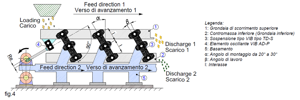
With high dynamic and inertial forces, and any time there is the need for an efficient and high-performance conveyor, we recommend that you use an oscillation system with mass and counter mass because stresses are never completely discharged in foundations but dynamically compensated by the two oscillating masses. Fig. 4 illustrates the diagram of a two-balanced-mass oscillating conveyor actuated by a connecting-rod/crank device. This plant consists of a chute supported by TD-S suspensions and actuated by TB or AD-P elastic element that acts as elastic joint (AD-P suggested in case of resonance condition application only). In this type of application crank shaft driven can be applied both on upper oscillating chute and lower counter mass. As alternative, TD-S can be replaced by TD-F which changes only in the fixing operation as shown in the following catalogue pages. The sliding channel (1) and the counter mass (2) have the same weight. Therefore, while oscillating, their two masses are dynamically balanced because one moves in the opposite direction to the other. This system also allows to take advantage of the counter mass oscillation to get a second sliding channel with the same direction of the upper one.
|
Usual feature for this type of plant |
|
|
Acceleration |
1,5 ÷ 5,0 g |
|
Feed speed |
10 ÷45 m/min |
|
Conveyor Lenght |
up to app. 25 m |
One-mass or two-mass-balanced oscillating conveyors can be designed to work under resonance dynamic regimen in order to increase the oscillation amplitudes and at the same time reduce the power required by the system. This condition however implicate a larger number of elastic suspensions compared to dynamic regimen out of resonance. VIB elastic elements provide the necessary dynamic elasticity to the system which can operate under resonance conditions but avoiding that vibrations propagate to the machine structure and, through the foundations, to the ground.